Device Memory Layout
The actual memory layout of a device is always hardware related. Nevertheless, Hornet specifies some common principles.
Special Requirement for MCU
There are some special memory layout for MCU.
- There are Flash memory and RAM, accessible with unified address. Code and initialized data are located in Flash memory.
- Certain data is required to be located to a certain fixed address, either in Flash or in RAM. For example, the NVIC table.
- Certain data is required to have special address alignment. It has to be aligned to the specified address boundary. For example, the DMA buffer.
- For some low power battery powered devices, even the RAM may be divided into different regions. Some region may be witout “retention”, meaning the content will be lost during low power deep sleep. In this case, the variable declaration may optionally specify region.
Firmware Memory Map
The firmware manages part of the RAM and Flash. Different MCU architectures have different memory layouts. On top of that, different applications may have alightly different memory map.
The memory map must be put into a header file and included in a required header file.
GNU Linker Script
For GCC, we use GNU linker script to define the memory layout.
Hornet releases a few sample linker scripts:
GCC Built-in Sections
The code generated by GCC is in ELF format. There are some built-in sections. Documentation is hard to find. At least there appears to be NO “official” one.
Here I’ve compiled some important ones that we must need.
- .text: code.
- .data: initialised data.
- .rodata: initialised read-only data.
- .bss: uninitialized data.
Here is a blog post I found with more detailed explaination.
MCU Is A Little Different
- We execute code directly from flash. As I said, flash memory is addressed in the same way as RAM (unified addressing), except that you can’t write to it.
- Please note the address we defined such as
_etext,_data,_edata,_bss,_ebss, as well as their relative locations. - Initialized readonly data (.rodata), which is defined as
const, resides on flash and will be addressed from flash. - Initialized data (variable) (.data) initially resides on flash. But it has to be copied to specific location on RAM during startup. It will then operates on RAM within the code.
- In above srcipt, the initialized data on flash starts from address
_etext. The RAM segment starts from_data. - As for
vtablesection, it is getting more ridiculous. GCC generates that as C++ vtable but there is almost no one even talked about it. It shall not be copied to precious RAM but obviously it is the way as of now. I found one discussion about it. BTW Hornet is written in C so there is zero vtable anyway.
- In above srcipt, the initialized data on flash starts from address
Other Notes:
_ebssis the start of the dynamic memory heap (as the end of uninitialized data). Those are explained in later paragraphs.- DMA control table must be placed on 1024 bytes address boundary. We place it to the start of RAM, which will be guaranteed to meet the requirement.
- There are 32 KB of memory. First 16KB is non-retention memory, which means the content will be lost during deep sleep. This firmware is not for battery powered devices. So we use the full 32KB starting from non-retention address.
GCC Optional section Attribute
GCC supports additional attributes with variable declaration.
For example, in the code below, we declare the variable to be placed in udma_channel_control_table section, which is the start of system RAM.
static volatile struct channel_ctrl channel_config[UDMA_CONF_MAX_CHANNEL + 1]
  __attribute__ ((section(".udma_channel_control_table")));
Flash Memory
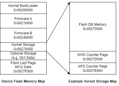
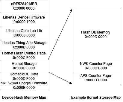
Diagram below are examples of flash memory map:
TI CC2538 with 512KB flash.

nRF52840

Read nRF52840 Dongle Programming Tutorial for more details.
Hornet Bootloader
Hornet shall have its own bootloader in order to provide unified and hardware independent user experience.
Bootloader works with firmware upgrade, reset and recovery.
- Hard reset from user will trigger bootloader OTA.
- User may instruct the bootloader to factory reset (clear clean application storage) in bootloader OTA mode.
- User may perform firmware upgrade in bootloader OTA mode. It gives user a chance to recover in case the current firmware is damaged.
- After the normal OTA from Hornet stack, the stack will mark the status on flash and perform a software reset.
- The bootloader will read the flag and perform further actions to switch to new firmware.
- Normally the bootloader simply jump to the current version of device firmware on flash.
Note, NRF52840 dongle is mainly used for testing purpose. Tt does not need a Hornet bootloader.
Firmware Memory
The executable code is stored in the device flash memory. Static const data is also compiled into code at pre-determined memory addresses.
Note in the example above, there are two firmware regions, Firmware A and Firmware B. In practice one region is the current “working” firmware while another region can be used for firmware upgrade.
There are certain control blocks in the flash to control which region is the current “working” one. Once the upgraded firmware is downloaded and verified, the device may rewrite the control block to “switch” over to the new firmware version and perform a hardware reboot.
On reboot, the Hornet bootloader will pick up the current “working” firmware region and boot into that region by a simple jump.
Note, we would recommend using an external flash to perform firmware upgrade. It will save nearly half of the on-chip flash. The benefit of dual firmware region is that it is easier to test on development board without external flash.
Hornet Storage Region
Hornet needs certain amount of flash memory to work properly. In the example region above, it demonstrates layout of a sample Hornet storage.
Hornet uses AES CCM encryption. Each message has a counter. The counter can only increase to avoid wireless replay-attack.
Hornet Flash DB
Hornet does not use a flash based file system. It has its own library Flash DB to store instances of C structs into flash.
For more information about flash DB, read the Flash DB library.
NWK and APS CCM Counters
In the example, we allocated two flash regions to store the NWK and APS counters.
If a device is equipped with SPI FRAM module, we can use FRAM to store the counters.
Developer’s Responsibility
Developer shall define macros corresponsing to the Hornet flash storage address and size.
Read Flash DB Developer Responsibility for Flash DB definitions.
For Hornet counters memory, if flash counter storage is used, HORNET_ARCH_FLASH_COUNTER must be defined. The folowing must be defined in a header referenced by hornet.h.
FLASH_HORNET_COUNTER_NWK_STARTFLASH_HORNET_COUNTER_NWK_ENDFLASH_HORNET_COUNTER_APS_STARTFLASH_HORNET_COUNTER_APS_END
Hornet Device MCU Data
A hornet device must store a structure called “Device MCU Data” into a fixed address of flash. It shall be generated by manufacture and shall be permantly stored.
#include "core/qw_device_info.h"
Below is the definitions:
BYTE_ALIGNED(
typedef struct qwha_rom_device_info_public_t {
    uint32_t			bootloader_version;
    uint64_t			manufacture_time;
    uint64_t			serial;									// Serial Number
    uint8_t				sku[QWHA_ROM_SKU_SIZE];							// Model name (32 bytes)
    uint8_t				signature[QWHA_CRYPTO_ED25519_SIGNATURE_SIZE];	// 64 Bytes
}) qwha_rom_device_info_public_t;

BYTE_ALIGNED(
typedef struct qwha_rom_device_io_t {
    port_pin_t			pin;
    uint8_t				pin_function : 7;
    uint8_t				pin_engage_pull_down : 1;
}) qwha_rom_device_io_t;

BYTE_ALIGNED(
typedef struct qwha_flash_device_info_t {
    qwha_rom_device_info_public_t	device_info_public;
    ecc_keys_t				device_key_pair;
    capability_information_t		capability;
    uint16_t				hardware_version;	// 20180906
    uint32_t				firmware_lo_addr;	// firmware needs to know the addresses
    uint32_t				firmware_hi_addr;
    uint32_t				firmware_size;
    uint32_t				storage_addr;
    uint32_t				storage_size;
    uint16_t				external_storage_1;
    uint16_t				external_storage_2;
    uint16_t				gui_type;
    uint32_t				gui_address;
    uint8_t					load_count;
    uint8_t					loads[QWHA_ROM_LOADS];
    uint8_t					button_count;
    qwha_rom_device_io_t		buttons[QWHA_ROM_BUTTONS];
    uint8_t					led_count;
    qwha_rom_device_io_t		leds[QWHA_ROM_LEDS];
    uint8_t					led_sequence[QWHA_ROM_LEDS];
    uint8_t					init_pin_count;
    qwha_rom_device_io_t		init_pins[QWHA_ROM_INIT_PINS];
    qwha_rom_device_io_t		load_pins[QWHA_ROM_LOADS];
    uint16_t				aux_ota_type_1;
    uint16_t				aux_ota_type_2;
    uint16_t				aux_ota_type_3;
    uint16_t				aux_ota_type_4;
}) qwha_flash_device_info_t;
Some fields in this data structure are essential.
For Bootloader
Bootloader requires some fields to work properly.
- Initialize GPIO pins - Some GPIO pins needs to be initialized immediately on startup, otherwise the device may be damaged.
init_pinsandinit_pin_countare used by Bootloader to perform the initialization. - LEDs - If device has LEDs. The bootloader may “flash” LED to indicate its current status.
ledsandled_countare used for that purpose. Note the order of LEDs inledsshall be arranged as well. - Hornet Storage Address and Size -
storage_addrandstorage_sizeenables Bootloader to reset the device by erasing the flash pages used by Hornet storage.
For Hornet Network Stack
- Device SKU - the
skufield is zero terminated string for further describe the device. We use github community to discuss the allocation of SKU prefixes to manufactrures. It is most efficient, open and fair way compared to current practices of big-teches. - Serial and Signature -
serialis a number assigned by manufactures.signatureis an Ed25519 digital signature generated by device manufacture. The signature can be used to verify the authenticity of the device solely on Hub side. - X25519 Key -
device_key_pairis an X25519 key pair generated by manufacture. The key pair is used by Hornet during device-join key exchange. Manufacture may keep the public key but MUST discard the private key for privacy reasons. Even if the manufacture keeps the private key, it usually won’t cause security problem but it will be unethical. The reason we depends on manufacture to generate the key pair is because the computing poewer of MCU is low and firmware size needs to be small.
RAM
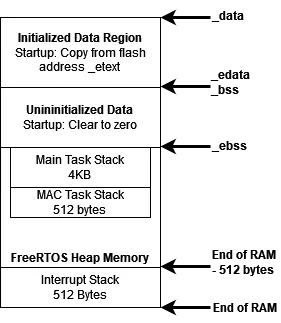
Below is an example of RAM map of a Hornet firmware running on FreeRTOS.

Initialized Data and Uninitialized Data
Initialized data is initially stored in flash memory. It shall be copied over to main RAM during in startup stub code.
Uninitialized data shall be cleared to zero.
Note, those addresses will be mapped to named variables by compiler. The mapping is defined in an “ld file”.
Cortex M Interrupt Stack
Cortex M uses dedicated stack for interrupt.
FreeRTOS will use the stack from the code that calls vTaskStartScheduler(), which is initialized as the first entry of NVIC table.
We initialized it to the end of RAM, which grows upward.
We reserved 512 bytes for the interrupt stack, which is proved sufficient.
Heap Memory
FreeRTOS requires application to initialize the memory block for heap (dynamically managed memory).
In our code, we shall allocate the entire memory block from end of uninitialized data (_ebss) to the boundary of interrupt stack (end_of_ram - 512 bytes).
Task Stacks
In FreeRTOS, each task has its own stack. The task stacks are dynamically allocated from heap. In our samples, we use 4KB for main task and 512 bytes for MAC task.